
The Raspberry Pi is a very versatile tool for any tinkerer. Lately there has been several projects where I wanted to include a Raspberry Pi, but did not have access to the correct voltage power supply. This turned me onto the idea of constructing a "hat" for the Pi that would serve as a power supply with a wide input voltage range.
Theory
The choice quickly lands on a switch-mode power supply, as a linear regulator would produce a lot of heat - probably enough to make it infeasible within the physical constraints. I had never before done a switch-mode circuit before, and decided it would be a fun challenge.
A quick way to approach a simple circuit like this is to pick a suitable component (in this case a switching voltage regulator) based on your needs and work it out from a reference design in the components data sheet.
In this case I used Mouser's component search and picked a component based on availability, and voltage and current capability.
Circuit Design
I ended up picking an adjustable variant of the LM2576 switching regulator. The adjustable variant was chosen because I've sometimes seen the Pi go into low voltage alarm when 5V supplies sag under load. I wanted the ability to fine tune the voltage to avoid this. As this is a learning project and not particularly designed for low cost a few extra components for variable voltage does not hurt.
Another thing that speaks for this particular component is its "monolothic" nature. A minimal number of components outside the integrated circuit is needed to complete the switching regulator.
Consulting the reference designs in the datasheet we quickly determine the minimum viable circuit:
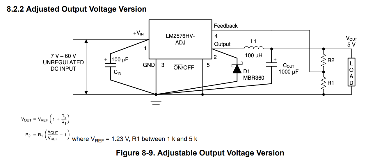
The circuit was then drawn up in KiCad so that a PCB layout can be made from it. The data sheet gives all the electrical and physical requirements, it is just a matter of understanding it, and trying to keep to it when designing the circuit and layout.
The core circuit includes two alternative ways to set the voltage (fixed or adjustable), and a power indicator LED.
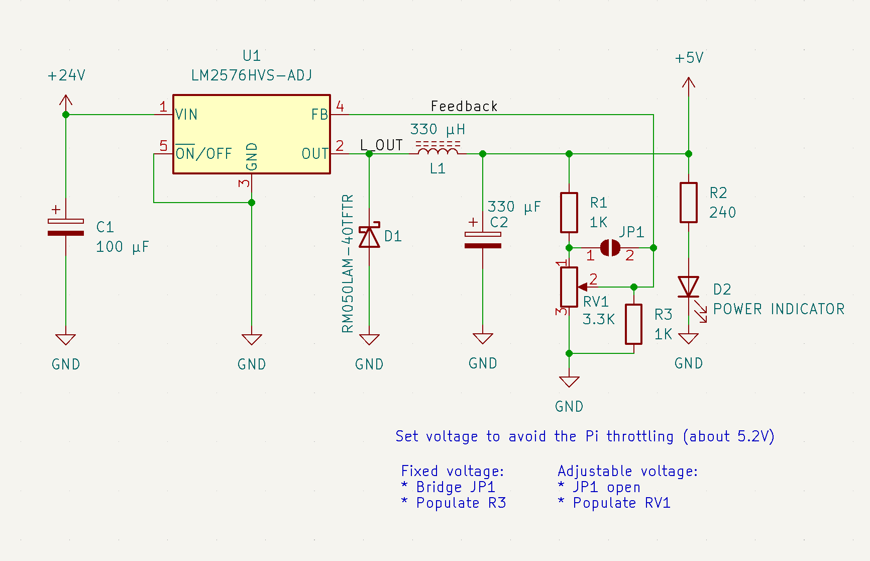
Additionally I included two alternative power input connectors, and some headers to allow access to the Pi's UART and SPI bus.
PCB Layout
PCB layout is about realizing the circuit and its features within the physical constraints. In this case I've chosen a so called Pi "hat", which means the device is meant to fit on top of the Raspberry Pi's headers. The mechanical drawings for Raspberry Pi are open, and from that we can extract the dimensions and spacing of mounting holes, as well as the placement of the pin headers.
I opted to include just enough of the pins for the functionality I wanted (power, UART and SPI). The only through-hole components in the layout are these pin headers, everything else is laid out with SMD footprints. It might have been possible to realize this circuit with only through-hole parts, but I find it easier to work with surface mount components.
When the physical board outline is set and the features that need to be in fixed positions are placed, you can start placing components. I decided to place the two power connectors on top of eachother. This makes it possible to solder either a screw terminal block or a barrel jack connector, and the use of "real-estate" is just for the barrel jack.
I started by making the bottom copper layer a GND fill. For the input and output power rails I also used fill zones instead of traces. Fill zones are nice as you get wide copper traces that have lower resistance - less heat and fewer losses. It also means the PCB manufacturer needs to etch away less copper.
Following the LM2576 datasheet the switching loop needs to be kept short, which dictated that the diode and inductor should be as close to the regulator as possible. This also includes the output capacitor, but I could not make room for that at the time. I compensated for that by making sure the copper fills were as wide as possible to reduce losses.
Also notice the "via stitching" on the GND pad of the switching regulator. This provides copper vias (essentially small tubes) directly down to the copper fill on the bottom, providing a way to wick heat away from the regulator onto the larger surface area of the PCB bottom layer. In hindsight it would probably not hurt to put even more of those in there.
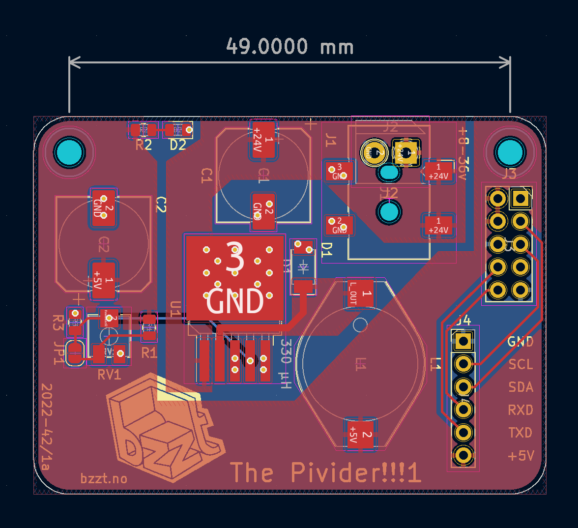
A friend of mine pointed out that R2 and D2 also were connected a long, long time ago in a galaxy far, far away. Obviously, the components therefore needed to be placed accordingly.
Fun logos, week and revision numbers are obligatory.
I then ordered a small batch of these boards from JLCPCB, the components from Mouser, and started clicking reload on the package tracking sites...
Testing
When everything had arrived I could put down some solder paste, place the components and put the PCB on the hot plate. Soldering is done in minutes!
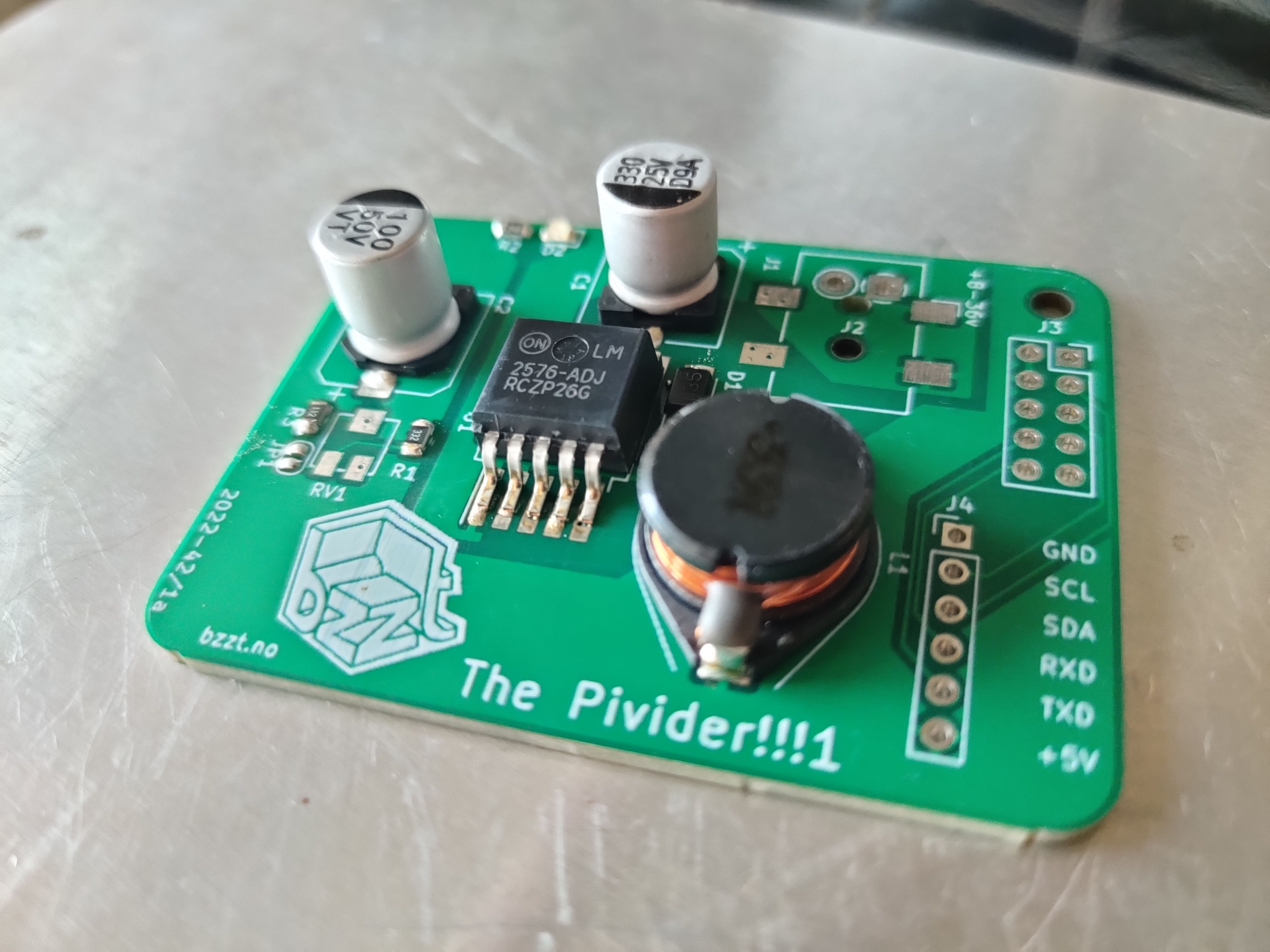
This is the part where you realize all your mistakes. The first one was obvious already while placing the components: I had picked a footprint for the capacitors that was too big. Oh well, the pins still reach. Could be worse.
And worse it got. It turned out, after weeks of waiting for the cheap postage, I had inverted the footprint of the Raspberry Pi headers. No Pies were harmed in the discovery of this mistake! I made it work by cutting som traces and placing some "bodge wires".
We can now adjust the voltage to about 5 volts and start some real testing.
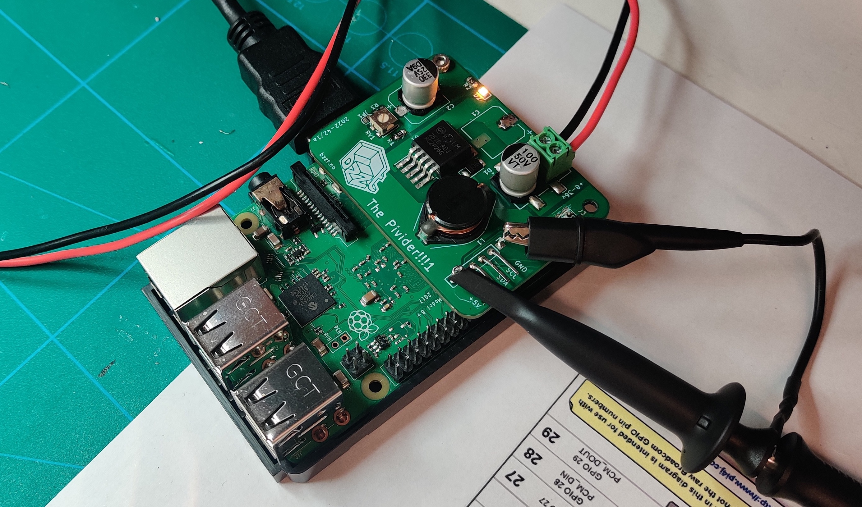
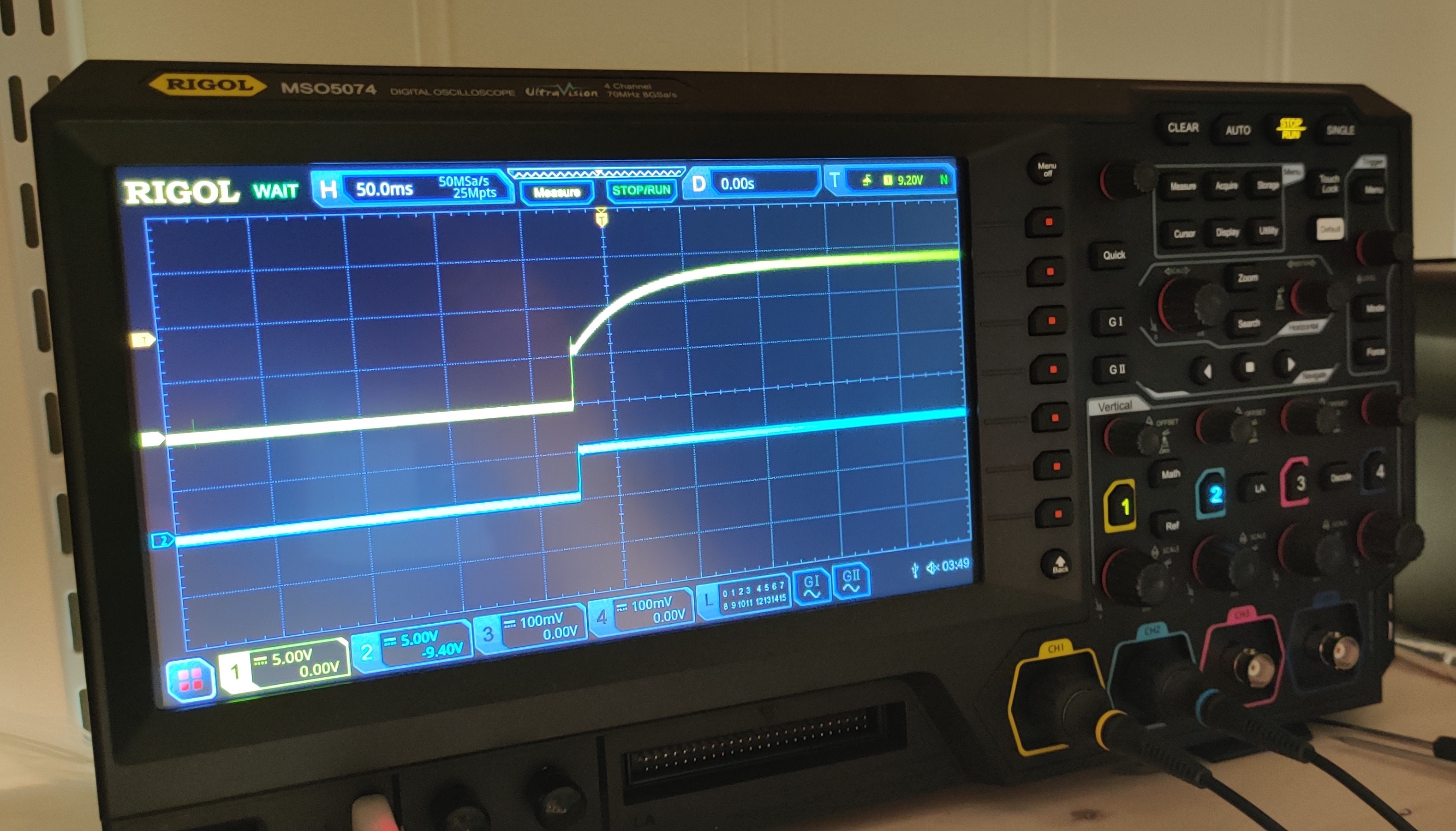
Connecting an oscilloscope to the PSU inputs and outputs we can make sure the output ripple voltage is within tolerable limits, and make sure there are no voltage spikes on powerup that may damage the device being powered.
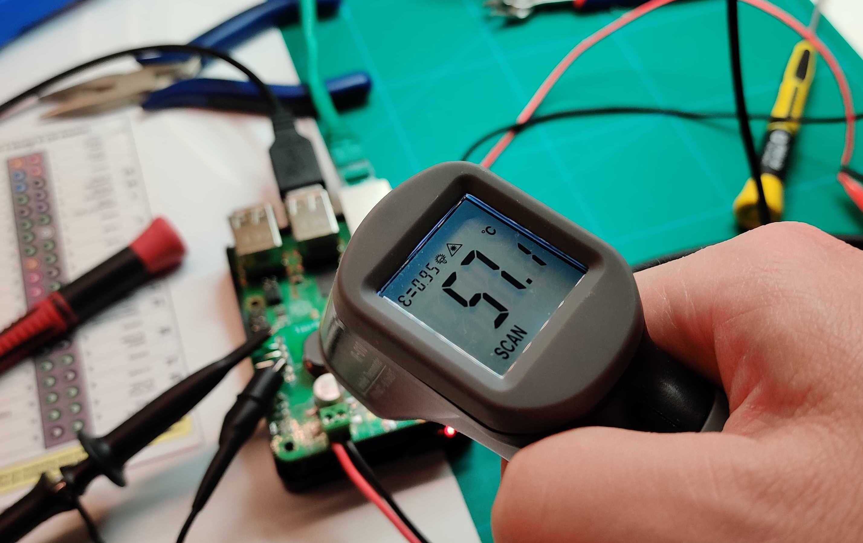
Then we load up the power supply by running the Pi's CPU at full tilt using stress and measure the temperature the PSU get to. The regulator will automatically shut down if the dye temperature gets too high, but we need to make sure the coil and diode also are up for it.
Conclusion
The components get a bit hot when stressed to the max, and the ripple could be better. I will have to revise the board since the header pinout is wrong, so I might as well make all the changes I want:
- Fix header pinout (inverted)
- Fix cap footprint size (they were too large)
- More footprints for output caps. Several caps can tune out noise better.
The power supply works, and I can easily use it to put a Raspberry Pi inside a 3D-printer or other project where there is usually only something like 12 or 24 volts available. The power supply should easily accept anywhere between 8 and 36 volts input.
There will probably be a post about the revised board in the future...